Currently, the thermal imaging visuals do not accurately or realistically respond to the provided attributes via https://community.bistudio.com/wiki/setTIParameter as expected.
Changes made via this do not produce expected results. As per https://community.bistudio.com/wiki/getTIParameters the output formula is as follows:
OutputRangeStart + thermalValue × OutputRangeWidth
Where "thermalValue" is the standin for "temperature" or the level of simulated thermal emissivity of a given surface. This value should be in a 0 to 1 range where 0 equals no emissivity (or minimum observable temperature) and 1 equals full emissivity (or maximum observable temperature.)
With the default values, which can be retrieved via getTIParameter, are as follows:
[["OutputRangeWidth",0.8],["UpdateHistogram",1],["FilmGrain",1],["OutputRangeStart",0.1],["Blur",1]]
The two relevant parameters here being "OutputRangeWidth" and "OutputRangeStart", utilizing the given formula, the expected default range should be 0.1 to 0.9
Visually, this means everything below 10% emissivity should be "cut off" or "clamped" and not appear in the final image, same for everything above 90% emissivity.
However, this is not what happens. Instead, it appears that the full visual range is present but the "exposure" is altered as if a post process filter is applied, so the full color range is simply forced into the desired range. The resulting output looks like what you might get if you altered the range of luminence with the "levels" filter in photoshop.
For example, if you wanted to limit the visual range to only the upper 12%, you'd use the following commands:
setTIParameter ["OutputRangeWidth", 0.125];
setTIParameter ["OutputRangeStart", 0.875];
Which should give and output range of 0.875 to 1.0, or the highest 12.5% of the thermal value.
With a thermal imaging device, you'd use temperature, but the principle is ultimately the same. This should show the full range of colors (complete black to complete white) but without displaying anything below 0.875 brightness.
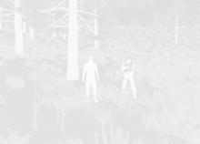
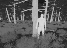
Instead, the result is as follows:
Not only is this incorrect, but by looking at the brightness of the human units vs the terrain objects, you can see that the contrast isn't properly adjusted. If we were seeing only the upper 12.5% of the thermal emissivity, you'd expect the trees, clutter, and surface to nearly impossible to see, if at all, where the human units should be nearly full brightness.
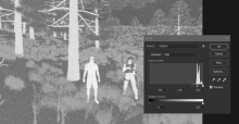
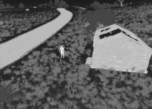
You can see here how the engine seems to incorrectly adjust the output range:
Which means the formula provided is incorrect, or selecting a slice of the visual range, as all thermal imaging devices that exist allow, isn't possible. Part of the reason for this could be that the parameters are restricted to the 0 and 1 range, which would obviously restrict what can be changed.
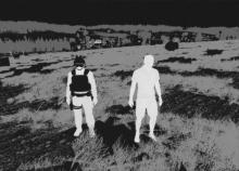
If I "normalize" the image in photoshop, The output looks like this:
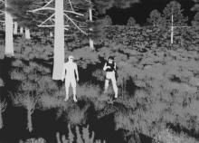
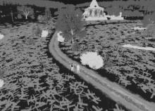
For comparison, here is how it looks with default, unaltered settings:
This issue is consistent across terrains, modded and vanilla, including my own terrain with custom lighting and tone mapping settings. This is true regardless of date, time, and weather conditions. There doesn't appear to be a way to address this via modding or scripting. The 0 and 1 limit for the TI parameters make this impossible to be fixed on the modder or mission maker side of things.
Graphics settings have no effect on the issue.
This thread makes some good observations as well.
PLEASE ask me for clarification, more info, more reference images, or ANYTHING that could help.
